Introduction
In this post, I attempt to elaborate the 5G project that I participated in. I want to explain the project and how it fulfills the requirements as concerns of system designs.
To explain requirements, I explain the bare minimum of 3GPP specifications and functions splits that the project abides.
For systems design concerns, I attempt to answer how the project satisfies some the questions such as:
- What is the scope of this system?
- How does the system server more customers, for this specific product, more data flow?
- How does the system transfer data internally/externally?
- How does the system handles bottleneck?
- How does the system support maintenance, future enhancement, defect fixing?
- What is the final high level design (HLD) for this system?
The final HLD incorporates all concerns in previous questions into its design. In this blog, I make use of 3GPP specifications, ORAN specifications, and some common industry designs without exposing the actual design of my company.
What is the scope of this projects.
5G communication system is the system the serves cellular network based on the technical standards provided by 3GPP.
3GPP organization also proposes protocol stack for 5G communication systems. In addition, they propose functional splits, which separate the implementation of those protocols in different logical nodes (devices), namely Centralized Unit (CU), Distributed Units (DU), Radio Units (RU).
The following diagram illustrates all the split options. We see that:
- Different 5G protocols server together Layer 1, Layer 2 and Layer 3, where those layers are corresponding to OSI model. For example, both MAC and RLC server as layer 2 functions.
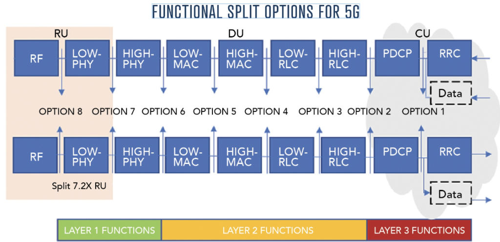
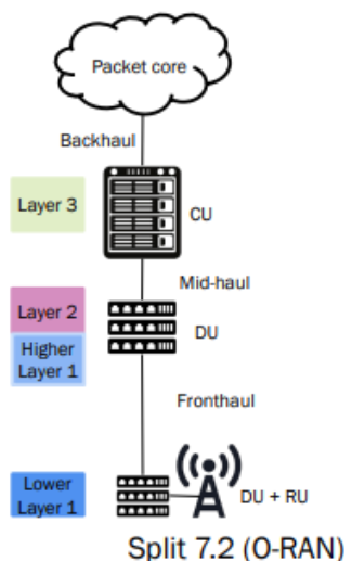
For various reasons, functional split 7.2 is the preferred choice and is proposed by ORAN alliance. The following diagram illustrates functional split 7.2. As a result, the DU nodes provides services of MAC and RLC protocol (Layer 2) and higher Phy (part of Layer 1)
According to 3GPP 38.322, the following are functions of RLC protocol:
- transfer of upper layer PDUs;
- error correction through ARQ (only for AM data transfer);
- segmentation and reassembly of RLC SDUs (only for UM and AM data transfer);
- re-segmentation of RLC SDU segments (only for AM data transfer);
- duplicate detection (only for AM data transfer);
- RLC SDU discard (only for UM and AM data transfer);
- RLC re-establishment;
- Protocol error detection (only for AM data transfer).
According to 3GPP 38.321, the following are functions of MAC protocol:
- mapping between logical channels and transport channels;
- multiplexing of MAC SDUs from one or different logical channels onto transport blocks (TB) to be delivered to
the physical layer on transport channels; - demultiplexing of MAC SDUs to one or different logical channels from transport blocks (TB) delivered from the
physical layer on transport channels; - scheduling information reporting;
- error correction through HARQ;
- logical channel prioritisation.
Without diving into the technical details, we could understand that the DU servers as a network server whose main function is to process and to transfer data according requirements of 2 protocols MAC and RLC. In addition, for sake for brevity, I only discuss the DU system that handle control plane operations, not user plane.
How does the system handle higher amount of data?
On horizontal scale, network providers increase the number of DUs to server more customer. For specific geographical region, there are tracking area that the users belong to. Going out of such region requires handover to different regions. By optimizing such regions and increasing the number of RUs, number of DUs that controls such RUs, and numbers of RU per tracking area, we could server more customers.
On vertical scale, the approach is done by improving the design of each DU. In this blog, I explain several improvements on our system.
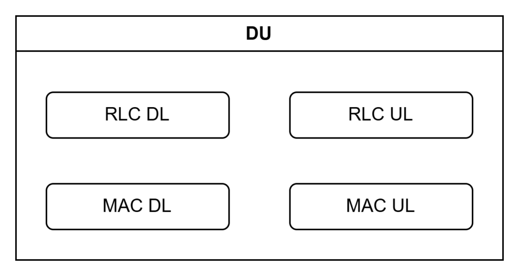
At the basic, we have a DU that has a least 4 modules to provide services of MAC and RLC on uplink and downlink traffic:
Utilizing multi-threads system:
As we have more customers, or incoming traffic, we need to have multiple threads to handle (control) traffics for each customer. We don't have unlimited memory, thus a threadpool management system, Thread_Mgr is required. When traffic from new user comes, a worker thread is initiated and invokes services provided by RLC or MAC.
Why threads are preferred over processes?
- Thread is lightweight, and costs less memory. Thread doesn't need copy of parent thread's memory to child's.
- Threads can access shared memory. In fact, each user's traffic is allocated a certain amount of memory from common memory pool. The total available memory pools are actually tightly coupled with not only the hardware memory of the DU but also the available radio resources. Thus our thread manager must communicate with another module that maintains or know the available radio resources.
Utilizing scheduling algorithm:
3GPP defines that user be assigned specific radio resources. The radio resources are allocated based on the service requirements (voice, video, IoTs etc) and radio condition (near, far, good or bad signal, crowed service etc).
3GPP also defines specifically that MAC protocol handles such a responsibility. Thus we need a dedicated MAC scheduler module to handle such tasks. MAC scheduler should have "good vantage point", meaning that it knows the total number of users and the available resources. Therefore, we have MAC_Scheduler as a singleton and another singleton module called DU-Mgr which maintains the total number of users, and the available resources. Du-Mgr also works with Thread_Mgr to spawn and close worker threads when needed.
The following illustrates the design that we have so far:
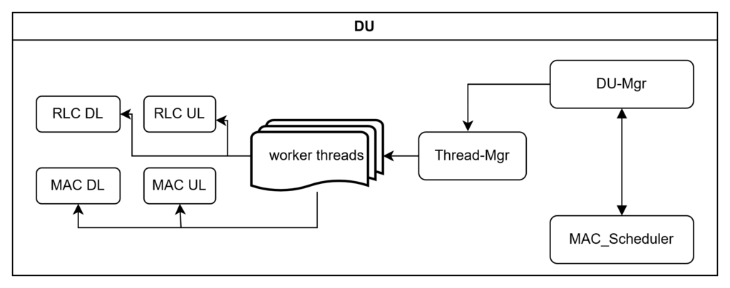
DU-Mgr: manages number of users, available resources for common services and dedicated server (per user service). Also invokes Thread-Mgr to call services for each users.MAC-Scheduler: assigns resources to users based on information of number of users and available resources.Thread-Mgrcreates worker threads when called upon byDU-Mgrwhen dedicated service is needed for each user.RLCandMACmodules provides services to each user's datagram on downlink and uplink traffic.
How does the system transfer data internally and externally?
External transferring of data:
3GPP defines F1 interface between DU and CU. According to 3GPP 38.470, the interface holds the following protocols IP and SCTP. The following illustrates the specification of F1 interface between DU and CU, regardless of functional split options.
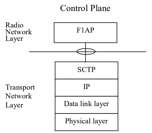
The Transport Network Layer (TNL) and Radio Network Layer (RNL) in 5G should not to be confused with Transport Layer and Network Layer in OSI model. TNL is responsible for transmitting the network packets between the NG-RAN nodes. RNL regards the control access to the mobile network. Thus we have MAC and RLC protocols in our DU contained within the Transport Network Layer. Above those protocols, we then have SCTP and IP. Consequently, if you capture a MAC data packets (called MAC PDU in 3GPP term), we would have SCTP header and IP header encapsulated within an RLC SDU, which is then encapsulated within MAC SDU. Adding MAC header to MAC SDU, we have a MAC PDU which is MAC data packets.
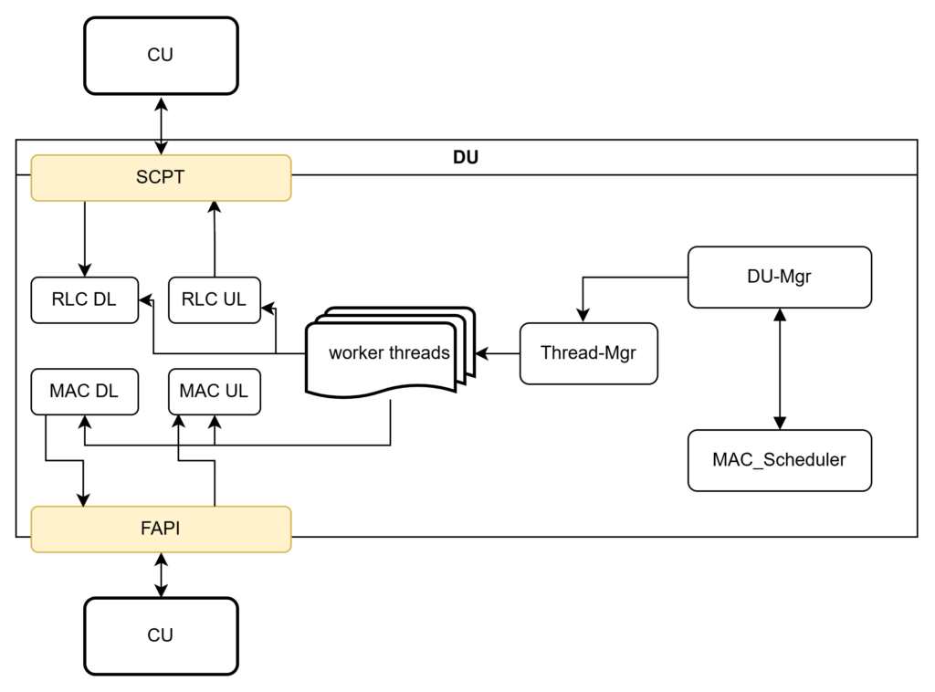
Our design should be updated with IP and SCTP module to handle services by those protocols. SCTP_IP module accepts data from upper layer (from CU) and transfer it downward to RLC_DL. SCTP_IP also accepts data from RLC_UL and transfer it to CU.
Likewise we also have FAPI module to handle data transferred from lower layer (RU) to DU.
The following diagram updates 2 external modules, with yellow color to handle external traffic from/to DU.
Internal transferring of data:
Traffic between internal modules are managed via several techniques:
- Messages Queues: handle service requests from workers threads and RLC, MAC.
- Worker thread invoke a request to RLC. The request is copied to a message queues and won't be handled until RLC finishes its earlier work. Upon receiving the request, RLC then can check its transmission buffer and pop outs from SCTP.
- Event Notification:
- We add another communication between SCTP and DU-Mgr, FAPI and DU-Mgr. There should be someway to inform DU-Mgr of incoming downlink or uplink traffic from user. The communication is handle via event notification.
- Likewise communication between DU-Mgr and MAC-Scheduler could also be implemented by Event Notifications.
- Between MAC and RLC, there are also event notification. According to 3GPP, it is responsibility of MAC_DL to inform RLC_DL of the next transmission opportunity. The transmission opportunity is defined as Transmission Interval Indicator (TTI). From MAC-Scheduler, MAC knows the downlink resources available for user, and thus can allocate the resources into each TTI. To be precise, the resources here is the transport block, or the amount of data that MAC can accept and transmit in each TTI. Thus when transmission opportunity is about to come, MAC should deliver an event notification that includes transport block sizes, TTI, and other relevant information to RLC so that RLC could send traffic downward.
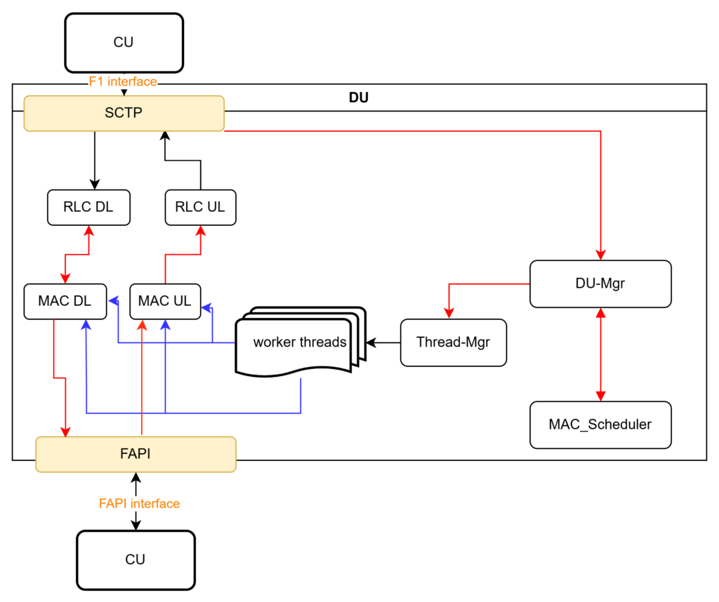
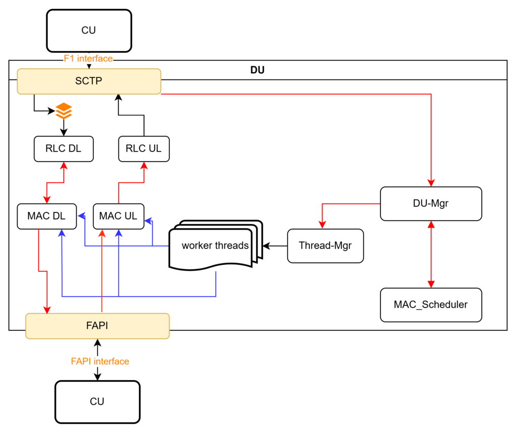
The following update the types of communication between modules. The red lines indicate communication by Events. The green lines indicate communication using Message Queues.
How does the system handle bottleneck?
From the above section, we can see that SCTP will feed data to RLC_DL continuously. SCTP does inform DU-Mgr of incoming traffic for certain users (as well as common control traffic). But at the same time traffic is also sent to RLC_DL.
3GPP suggest that for data for user in (Unacknoledged mode) UM and (Acknowledged Mode) AM mode, a transmission buffer should be implemented. The buffer stores (user) data from SCTP and only pop up data when RLC receives service request from worker thread.
How does the system handle operation maintenance needs?
By "operation maintenance" I mean, the system needs to be able to provide:
- logs for debugging.
- performance counter to indicates area for future enhancement.
For log debugging: DPDK provides a great tool to log critical data in each packets such as those on headers. DPDK itself is a set of libraries and drivers for fast packet processing. Thus a could have a module to support turning on different level of logs. The module then utilize external library DPDK.
Performance counters are suggested by 3GPP 38.552, 38.554, an ORAN. The performance counter should be triggered within MAC and RLC modules because those module perform core services of DU.
Operation Administration and Maintenance (OAM) is a module outside DU that performs management of the whole NG-RAN, including DU, CU, and RU. Thus, while we add codes to implement trigger counter calculation within RLC and MAC, the counter themselves should be managed by OAM, outside DU.
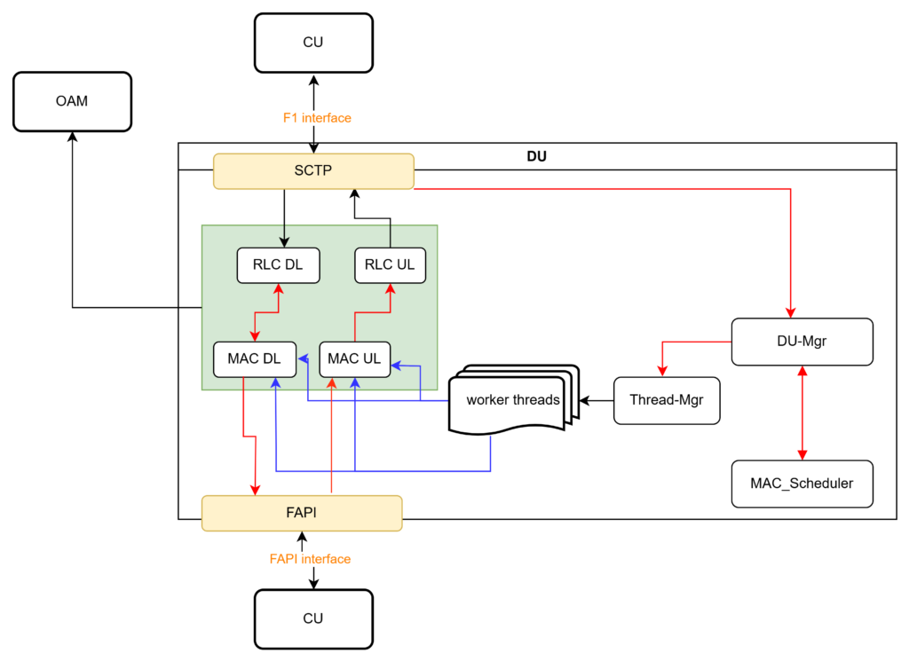
Now we are ready to add OAM to our design:
Final HLD
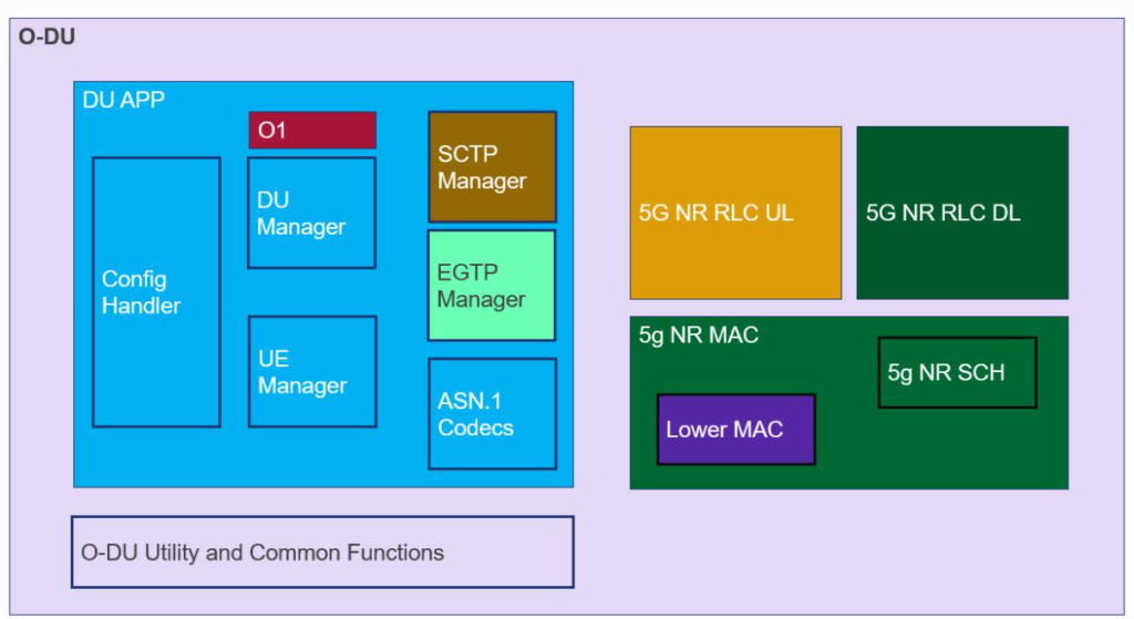
This is the final basic design the concludes this blog post. Keep in mind that the design only supports control plane, that includes common control messages and user dedicated control messages.
To conclude this blog, I bring up the suggested design by ORAN, without explaining the details. This diagram illustrated all the components that supports both user plane and control plane traffic.