
Introduction
This blog starts a series of blog posts about 5G architecture defined by 3GPP and O-RAN. Open RAN is the industry’s generic term for an open radio access network architecture.
In part 1, I will start with explaining overall 5G NG-RAN architecture to recap the basic interfaces between 5G nodes in this blog.
In part 2, I will also briefly discuss in the next blog a bit of O-RAN Overall Architecture, which are detailed in O-RAN white papers.
Within O-RAN architecture is CU, DU and RU, which are implemented based on functionality splits. My previous blog recaps the split options.
In part 3, after having the big picture, I will explain about CUSM Plane which includes the messages between DU and RU.
This blog is written with the aim to provide "cheet sheet", "quick reminder". It will only summarize, recap some basic concepts and refer to official documentation. It does not mean to replace the official documentation or more technical blogs but to help readers to recall basic concepts and find relevant information.
5G NG-RAN overall architecture and interfaces
Our starting point is TS.38.401: NG-RAN Architecture.
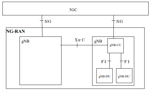
- The NG-RAN consists of a set of gNBs connected to the 5G Core through the NG interface, which supports the exchange of signalling information between the NG-RAN and 5GC. Ref: TS 38.143
| Responsibilities | Sample Messages |
| PDU Session Management | PDU Session Establishment Request (UE->AMF) |
| UE Context Management | Initial Context Setup Request (AMF-> gNB) |
| Mobility Management | Hand Over Command (AMF-> source gNB) |
| Paging | Paging (AMF-> gNB) |
| transporting NAS messages (msg between UE and Core). | Initial UE Message (gNB -> AMF) |
| interface management | NG Setup (gNB -> AMF) |
- Between the gNBs, the communication is via Xn interface, which allows interconnecting NG-RAN nodes (gNB). Ref: Xn protocol messages defined in TS 38.423
| Responsibilities | Sample Messages and direction |
| Mobility Management | Handover Request (gNB source->gNB target) |
| Paging | RAN Paging (gNB source->gNB target) |
| Dual connectivity to an eNB | |
| interface management | Xn Setup Request (gNB -> gNB) |
- gNB nodes are further separated into RU, CU and DU. Communication between CU and DU are via F1 interface. Ref: TS 38.473
| Responsibilities | Sample Messages and direction |
| UE Context Setup | UE Context Setup Request (CU-> DU) |
| Paging | Paging (CU->DU) |
| RRC Messages transfer | UL/DL RRC message transfer |
| System Infomation Deliver | System Information Delivery Command |
| interface management | F1 Setup Request (DU-> CU)GNB-DU Configuration Update (DU->CU) |
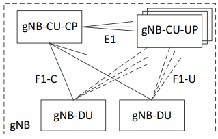
- a gNB may contain 1 control plane CU , multiple user plane CU, and multiple DU. The gNB-CU-UP is connected to the gNB-CU-CP through the E1 interface. Ref: TS 38.463
| Responsibilities | Sample messages and direction |
| Bearer Context Setup | Bearer Context Setup Request (CU control plane -> CU user plane) |
| Interface management | GNB-CU-UP E1 Setup Request (CU control plane -> CU user plane)Reset (CU control plane -> CU user plane or CU user plane -> CU control plane ) |
References
TS 138 401: " NG-RAN Architecture description"
TS 138 413: "NG Application Protocol"
TS 138 423: "Xn Application Protocol"
TS 138 473: "F1 Application Protocol"
TS 138 463: "E1 Application Protocol"
Blog post describing 5G interfaces and references to 3GPP specifications: 5G NR network interfaces-Xn,NG,E1,F1,F2 interface types in 5G (rfwireless-world.com)